next up previous contents index
Avanti: Filtro di Hilbert Su: Rappresentazione dei segnali modulati Indietro: Inviluppo complesso e modulazione di ampiezza   Indice   Indice analitico

Componenti analogiche di bassa frequenza

L'inviluppo complesso $ \underline{x}$$ \left(\vphantom{ t}\right.$t$ \left.\vphantom{ t}\right)$ = a$ \left(\vphantom{ t}\right.$t$ \left.\vphantom{ t}\right)$ej$\scriptstyle \varphi$$\scriptstyle \left(\vphantom{ t}\right.$t$\scriptstyle \left.\vphantom{ t}\right)$ può ovviamente essere espresso tramite le sue parti reale ed immaginaria: $ \underline{x}$$ \left(\vphantom{ t}\right.$t$ \left.\vphantom{ t}\right)$ = a$ \left(\vphantom{ t}\right.$t$ \left.\vphantom{ t}\right)$cos$ \varphi$$ \left(\vphantom{ t}\right.$t$ \left.\vphantom{ t}\right)$ + ja$ \left(\vphantom{ t}\right.$t$ \left.\vphantom{ t}\right)$sin$ \varphi$$ \left(\vphantom{ t}\right.$t$ \left.\vphantom{ t}\right)$ = xc$ \left(\vphantom{ t}\right.$t$ \left.\vphantom{ t}\right)$ + jxs$ \left(\vphantom{ t}\right.$t$ \left.\vphantom{ t}\right)$. I segnali xc$ \left(\vphantom{ t}\right.$t$ \left.\vphantom{ t}\right)$ = a$ \left(\vphantom{ t}\right.$t$ \left.\vphantom{ t}\right)$cos$ \varphi$$ \left(\vphantom{ t}\right.$t$ \left.\vphantom{ t}\right)$ ed xs$ \left(\vphantom{ t}\right.$t$ \left.\vphantom{ t}\right)$ = a$ \left(\vphantom{ t}\right.$t$ \left.\vphantom{ t}\right)$sin$ \varphi$$ \left(\vphantom{ t}\right.$t$ \left.\vphantom{ t}\right)$ prendono il nome di componenti analogiche di bassa frequenza di x$ \left(\vphantom{ t}\right.$t$ \left.\vphantom{ t}\right)$ per un motivo presto chiaro. Intanto sviluppiamo8.10 l'espressione del corrispondente segnale modulato:

x$\displaystyle \left(\vphantom{ t}\right.$t$\displaystyle \left.\vphantom{ t}\right)$ = $\displaystyle \Re$$\displaystyle \left\{\vphantom{ \underline{x}\left( t\right) e^{j\omega _{0}t}}\right.$$\displaystyle \underline{x}$$\displaystyle \left(\vphantom{ t}\right.$t$\displaystyle \left.\vphantom{ t}\right)$ej$\scriptstyle \omega_{0}$t$\displaystyle \left.\vphantom{ \underline{x}\left( t\right) e^{j\omega _{0}t}}\right\}$ = a$\displaystyle \left(\vphantom{ t}\right.$t$\displaystyle \left.\vphantom{ t}\right)$cos$\displaystyle \left(\vphantom{ \omega _{0}t+\varphi \left( t\right) }\right.$$\displaystyle \omega_{0}^{}$t + $\displaystyle \varphi$$\displaystyle \left(\vphantom{ t}\right.$t$\displaystyle \left.\vphantom{ t}\right)$ $\displaystyle \left.\vphantom{ \omega _{0}t+\varphi \left( t\right) }\right)$ = a$\displaystyle \left(\vphantom{ t}\right.$t$\displaystyle \left.\vphantom{ t}\right)$$\displaystyle \left[\vphantom{ \cos \omega _{0}t\cos \varphi \left( t\right) -\sin \omega _{0}t\sin \varphi \left( t\right) }\right.$cos$\displaystyle \omega_{0}^{}$tcos$\displaystyle \varphi$$\displaystyle \left(\vphantom{ t}\right.$t$\displaystyle \left.\vphantom{ t}\right)$ - sin$\displaystyle \omega_{0}^{}$tsin$\displaystyle \varphi$$\displaystyle \left(\vphantom{ t}\right.$t$\displaystyle \left.\vphantom{ t}\right)$ $\displaystyle \left.\vphantom{ \cos \omega _{0}t\cos \varphi \left( t\right) -\sin \omega _{0}t\sin \varphi \left( t\right) }\right]$
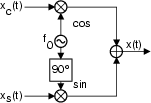
  = xc$\displaystyle \left(\vphantom{ t}\right.$t$\displaystyle \left.\vphantom{ t}\right)$cos 2$\displaystyle \pi$f0t - xs$\displaystyle \left(\vphantom{ t}\right.$t$\displaystyle \left.\vphantom{ t}\right)$sin 2$\displaystyle \pi$f0t

0.350000
\resizebox* {0.35\columnwidth}{!}{\includegraphics{cap8/f8.13.ps}}


\resizebox* {0.25\columnwidth}{!}{\includegraphics{cap8/f8.14.ps}}

Il risultato ottenuto è valido per un qualunque segnale; ma riveste una importanza particolare nel caso in cui x$ \left(\vphantom{ t}\right.$t$ \left.\vphantom{ t}\right)$) sia di tipo limitato in banda con banda 2W centrata attorno ad f0, con W < f0: in tal caso, sia xc$ \left(\vphantom{ t}\right.$t$ \left.\vphantom{ t}\right)$ che xs$ \left(\vphantom{ t}\right.$t$ \left.\vphantom{ t}\right)$ risultano limitate in banda tra $ \pm$W e contigue all'origine.

Che sia vero anche il viceversa, può essere verificato in modo intuitivo, partendo da xc$ \left(\vphantom{ t}\right.$t$ \left.\vphantom{ t}\right)$ e xs$ \left(\vphantom{ t}\right.$t$ \left.\vphantom{ t}\right)$ limitate in banda, e moltiplicandole per coseno e seno. Quest'ultima osservazione ci mostra una via per sintetizzare un segnale modulato in ampiezza, od angolarmente, od entrambe le cose, mediante il semplice schema circuitale disegnato a fianco, che si basa sulla conoscenza delle componenti analogiche di bassa frequenza, che a loro volta sono ottenibili a partire da a$ \left(\vphantom{ t}\right.$t$ \left.\vphantom{ t}\right)$ e $ \varphi$$ \left(\vphantom{ t}\right.$t$ \left.\vphantom{ t}\right)$. Restano comunque (per ora) aperti i seguenti problemi:

Per procedere oltre occorre introdurre:


next up previous contents index
Avanti: Filtro di Hilbert Su: Rappresentazione dei segnali modulati Indietro: Inviluppo complesso e modulazione di ampiezza   Indice   Indice analitico
alef@infocom.uniroma1.it
2001-06-01